Por favor introduzca la cantidad deseada y pulse sobre el carrito.
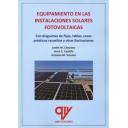
This is a second edition of a comprehensive Specification providing minimum requirements for the post-tensioning system component testing and acceptance, design, and installation of multistrand and grouted post-tensioning systems. Based on proven knowledge and developed with the ANSI consensus process, it addresses the selection of tendon protection levels
This is a second edition of a comprehensive Specification providing minimum requirements for the post-tensioning system component testing and acceptance, design, and installation of multistrand and grouted post-tensioning systems. Based on proven knowledge and developed with the ANSI consensus process, it addresses the selection of tendon protection levels, system components, materials, installation, and stressing of post-tensioning tendons. It provides requirements and guidance for furnishing complete post-tensioning systems and all required accessories, including but not limited to anchorages, local zone reinforcement, ducts, pipes, strands, and bars from a single supplier, as required. Provisions further address submittal samples, drawings, calculations, procedures, reports, manuals, and certifica¬tions. Both temporary and permanent post-tensioning is covered in this Specification.
This Specification should be used in its entirety to avoid unnecessary differences in requirements and provisions out of context. It is primarily intended for use in bridges but is also applicable to a wide variety of structure types, including buildings. The companion document PTI M55.1, Specification for Grouting of Post-Tensioned Structures, should be used in conjunction with this document.
One of the major features of this edition is the addition of a Commentary that provides guidance for most mandatory provisions of the Specification. Grouting related items that are installed with the ducts are now included. The PT duct provisions are expanded to allow for use of either fib Bulletin 7 or 75, depending on project needs. Pourback details are provided in the Appendix. Many other provisions received smaller revisions.
Table of Contents
1 INTRODUCTION
1.1 General description
1.2 Alternative post-tensioning scheme
1.3 Referenced standards and specifications
2. DEFINITIONS AND ABBREVIATIONS
2.1 Definitions
2.2 Abbreviations
3 POST-TENSIONING SYSTEM (PTS) TENDON PROTECTION LEVELS (PL)
3.1 Protection Level 1A (PL-1A)
3.2 Protection Level 1B (PL-1B)
3.3 Protection Level 2 (PL-2)
3.4 Protection Level 3 (PL-3)
4. MATERIAL AND PERFORMANCE REQUIREMENTS
4.1 General
4.2 Material standards
4.2.1 Strand
4.2.2 Bar
4.2.3 Special prestressing materials
4.3 Component standards
4.3.1 General
4.3.2 Post-tensioning anchorages
4.3.3 Permanent grout caps
4.3.4 Bar couplers
4.3.5 Duct
4.3.5.1 Corrugated metal duct
4.3.5.2 Corrugated plastic duct
4.3.5.3 Smooth HDPE duct
4.3.6 Duct connections and fittings
4.3.7 Heat-shrink sleeves
4.3.8 Precast segmental duct couplers
4.3.9 External smooth HDPE duct connections
4.3.10 Rigid ducts and steel pipes
4.3.11 Connection tolerance between pipe and duct
4.3.12 Inlets, outlets, valves, and plugs
4.4 System approval testing
4.4.1 Post-tensioning anchorages
4.4.2 Grouting component assembly pressure test (PL-1B, PL-2, and PL-3 only) and system safety proof test (PL-1A only)
4.4.3 Duct testing
4.4.4 Corrugated plastic duct
4.4.5 System pressure tests
4.4.5.1 Corrugated plastic duct connections
4.4.5.2 Precast segmental duct couplers
4.4.5.3 Internal duct systems
4.4.5.4 External duct systems
5. INSTALLATION DRAWINGS AND STRESSING CALCULATIONS
5.1 General
5.2 System drawings
5.3 Tendon drawings
5.3.1 Plans and elevations
5.3.2 Sections
5.3.3 Measurements
5.3.4 Tolerances
5.3.5 Stressing data
5.3.6 Material take-off
5.3.7 Temporary openings for PT work
5.3.8 — Installation requirements
5.4 Stressing calculations
6. QUALITY ASSURANCE AND QUALITY CONTROL (QA/QC)
6.1 QA program
6.2 Procurement
6.3 Project quality plan
6.4 Receiving
6.4.1 Wedges
6.4.2 Prestressing steel
6.4.3 Anchorages
6.5 Identification and traceability of materials
6.6 Sampling of prestressing material
6.7 Defects during installation
7.PERSONNEL QUALIFICATIONS
7.1 Supervision
8. SHIPPING AND STORAGE OF MATERIALS
8.1 General
8.2 Anchorages
8.3 Wedges
8.4 Metal duct
8.5 Plastic duct
8.6 Strand
8.7 Bars
8.8 Cement and grout
8.9 Accessories
9. BEARING PLATE AND DUCT INSTALLATION
9.1 General
9.2 Measurements
9.3 Tolerances
9.4 Anchorage components
9.5 Deviation pipes
9.6 Ducts
9.7 Accessories
9.8 Splices and joints
9.9 Location of grout inlets and outlets
10.PLACING CONCRETE
10.1 Precautions
10.2 Proving of post-tensioning ducts
10.3 Problems and remedies
11. PRESTRESSING STEEL INSTALLATION
11.1 General
11.2 Strand
11.3 Bar
11.4 Corrosion protection
11.5 Acceptance criteria
12. STRESSING OPERATIONS
12.1 General
12.2 Maximum stress at jacking
12.3 Stressing sequence
12.4 Stressing jacks and gauges
12.5 Calibration of jacks and gauges
12.6 Elongations and agreement with forces
12.7 Friction testing
12.8 Wire failures in strand tendons
12.9 Cutting of post-tensioning steel
12.10 Capping of tendons
12.11 Record of stressing operations
13.GROUTING OPERATIONS
13.1 Duct air test
14.PROTECTION OF POST-TENSIONING ANCHORAGES
14.1 General
14.2 Pourbacks
14.3 Anchorage coating system
15.REPAIRS OF HOLES AND ACCESS OPENINGS
15.1 Openings
16.REFERENCES
APPENDIX A TYPICAL POURBACK DETAILS AND INLET AND OUTLET DETAILS
APPENDIX B TYPICAL REPAIR DETAILS FOR ACCESS OPENINGS, BLOCKOUTS, AND HOLES